
Summary of all activities of Metallic Construction Materials group is here.
Principle of computed tomography
Computed tomography is a non-destructive imaging method capable of creating a 3D model of the scanned object showing its external and internal structure. X-ray passes through the scanned object to the detector and is partially absorbed. Information about the scanned object is obtained based on the amount of absorbed radiation. A large number of these projections are made, and the sample is gradually rotated after the individual images are taken until a 360° rotation is achieved. Individual sections of the material and a 3D model composed of groups of points, so-called voxels, are then created by the mathematical composition of the obtained data.
X-ray absorbance depends on the density of the material. Less dense materials with a lower proton number absorb only a smaller fraction of X-rays and appear dark in the images. Denser materials with a high proton number absorb X-rays more and, on the contrary, appear bright in the images. In order for the radiation to penetrate through materials with higher absorbance, it is necessary to apply a higher electrical voltage during its generation, which broadens the spectrum of X-ray radiation and achieves a higher penetration ability.
Equipment
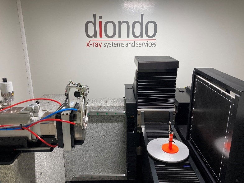
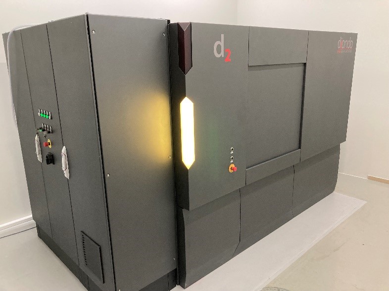
The Diondo d2 microtomograph, which is available in the Technopark Kralupy, is capable of scanning at a resolution of up to 2 μm. It is equipped with a transmission tube capable of working at a voltage of up to 225 kV, a flat detector with a size of 417 × 417 mm, and a rotary table with a load capacity of up to 20 kg. The VGStudio 3.4. program is used for data processing.
|
|
 |
| Microtomograph Diondo d2 | Interior of Diondo d2 microtomograph |
Possibilities of computed microtomography
Computed microtomography has a wide range of applications in the analysis of the internal structure of a material. The non-destructive nature and relatively short measurement time, combined with the universality for different types of materials, make this method interesting for various applications in material research.
The size of the sample that can be observed depends on the type of material. Samples from light materials (e.g., polymers) can have a thickness of up to 20 cm in full cross-section, while for example steel samples can only be examined at a thickness of less than 2 cm in full cross-section due to their higher absorbance. Approximate values of maximum material thicknesses are summarized in the table below.
|
Material |
Maximal thickness [mm] |
|
Polymer |
220 |
|
Aluminium |
120 |
|
Light ceramics |
140 |
|
Steel |
20 |
Analysis of internal material defects
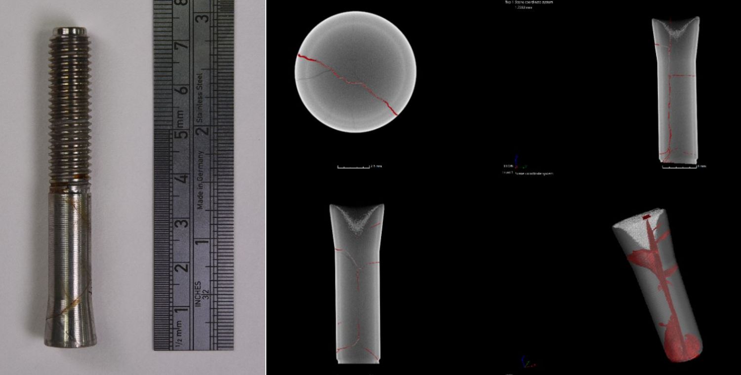
With the help of microtomography, internal material defects can be visualized with relatively high accuracy and their size and morphology can be described. These defects include cracks, shrinkage, pores, cavities, etc. Software tools for data processing allow to create a whole range of visualizations that facilitate the interpretation of the obtained results. A few examples are given below.
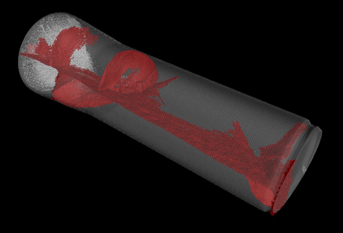
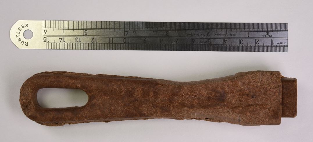
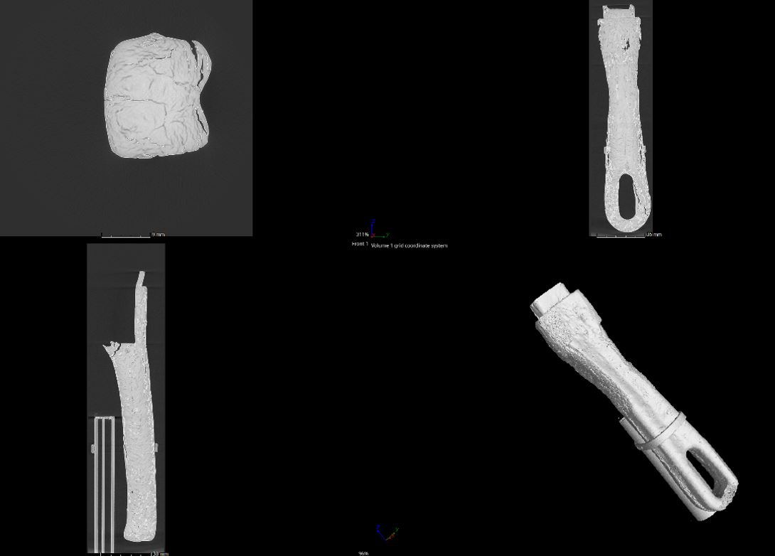
The first set of images shows a climbing anchor that has developed a crack due to corrosion cracking. As seen from the images, the crack passes through the entire volume of the sample and has a branched morphology. Although the anchor did not fracture in this case, the material will no longer exhibit the required mechanical properties.
|
|
|
|
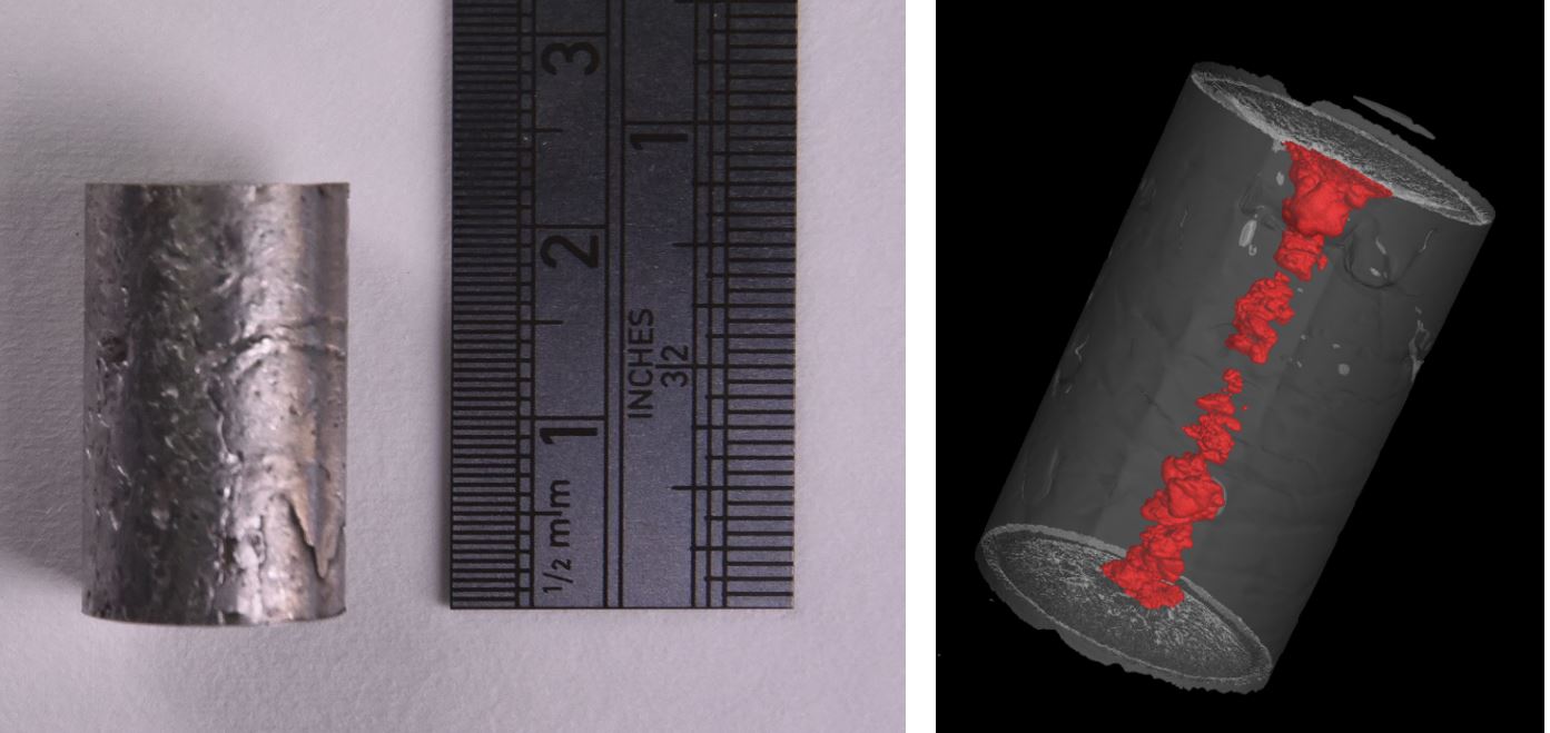
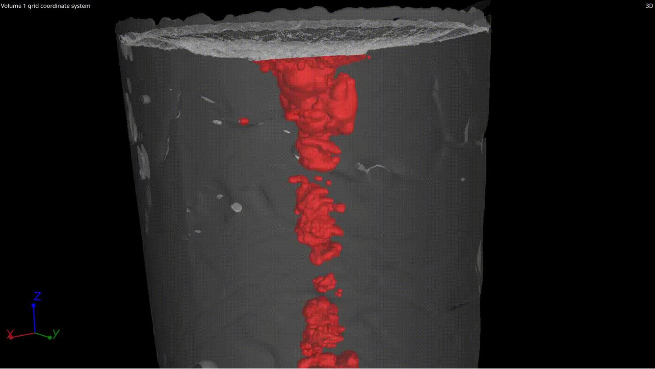
The second set of images shows a casting of the high entropy alloy CoCrFeNiMn. These alloys show some interesting mechanical properties, but when processed by casting, they contain a significant amount of shrinkage, which is highlighted in red in the images. The shrinkages can be well recognized and described using computed tomography.
|
|
|
|
Computed microtomography can also be used for quality control of industrial products. The pressed product in the following picture contains a large number of cracks and was therefore not processed by the correct procedure.
|
|
|
|
Multimaterial analyses
As mentioned above, the absorbance of X-ray radiation depends on the proton number or the density of the material. This can be used when examining samples composed of several types of material. By analysing the gray levels, i.e., the intensity of the radiation weakened by passing through the scanned object, we can distinguish the individual materials in the images. An example is the image below showing a polymer filter composed of materials of different densities.
|
|
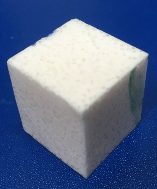 |
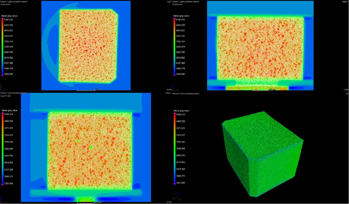
Determination of material porosity
Due to the ability to distinguish different types of materials, pores in the internal structure of the sample can also be distinguished. This is useful for determining total porosity, especially in the case of closed pores.
Shape and size comparison
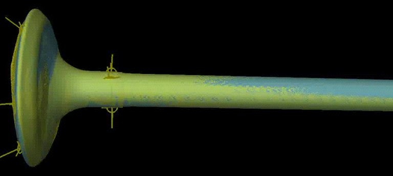
Computed microtomography provides images with comparatively high resolution (µm to tens of µm). This can be used to compare the shape and size changes of different components due to wear, formation of deposits or corrosion products. The visualization shows engine intake valves after production and after years of service when in some places the dimensions of the valve are larger due to the formation of deposits. Similarly, it is possible to compare finished products with a CNC or a 3D printing model.
|
|
About us
Technopark Kralupy is a spin-off of The University of Chemistry and Technology Prague serving the Czech and international industry in the field of building chemistry and similar subjects since 2015.
Contact
Department of Metallic Construction Materials
Technopark Kralupy of the University of Chemistry and Technology Prague
Technopark Kralupy VŠCHT Praha
Náměstí G. Karse 7
278 01 Kralupy nad Vltavou
Czech Republic
kovy@technopark-kralupy.cz
Phone: +420 220 446 104, +420 723 242 413
© 2022–2024 Technopark Kralupy